



Products

The SK730X safety pressure relief/holding valve is controlled by a pilot valve and includes an adjustable pressure relief/holding pilot valve, needle valve, small filter, and ball valve.
When installing a safety pressure relief valve: The valve is connected to the bypass branch pipe, with its outlet leading to the low-pressure area or drainage ditch. Normal water flow continuously enters the upper control chamber 2 through needle valve 1 via the main valve inlet. The pilot valve 3 is set to the predetermined pressure value A; when the pressure upstream of the valve falls below this value, the pilot valve remains closed, and the pressurized water in the upper control chamber 2 forces the diaphragm to lower the valve disc, thereby closing the main valve. When the pressure upstream exceeds the set value A, the pilot valve opens upon detecting the pressure increase, releasing pressure from the upper control chamber 2. The main valve disc then opens under the action of the upstream pressurized water to discharge water, ensuring that the pipeline pressure remains below the preset safety threshold A.
When operating the pressure relief valve: The valve is connected in series with the main pipeline to ensure that the water supply pressure upstream reaches a predetermined set value B. Normal water flow continuously enters through needle valve 1 from the main valve inlet.
In the upper control chamber 2, the pilot valve 3 is adjusted to the set pressure value B. When the pressure upstream of the valve falls below this set value, the pilot valve remains closed; the pressurized water entering the upper control chamber 2 forces the diaphragm to move the valve disc downward, closing the main valve to store pressure and ensuring the upstream pressure reaches value B. When the upstream pressure exceeds the set value, the pilot valve opens upon detecting the pressure rise, releasing pressure from the upper control chamber 2, and the main valve disc opens under the action of the upstream pressure water to discharge water, thereby maintaining the pipeline pressure at the set safety value B.
Parameter/Standard
● Style classification: Flanged safety pressure relief and holding valve ● Implementation standard: JB/T 10674
● Working pressure: PN10/16125
● Interface type: Should be installed horizontally
Material list
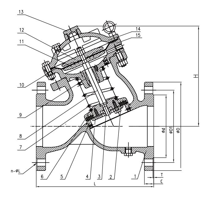
order number | part | standard layout |
1 | valve body | Ductile cast iron QT450-10 |
2 | Main port sealing gasket | Ethylene Propylene Diene Monomer (EPDM) rubber |
3 | Valve disk pressure cap | Stainless steel 304 |
4 | Valve disk pressure plate | Ductile cast iron QT450-10 |
5 | valve seat | Stainless steel 304 |
6 | valve disk | Ductile cast iron QT450-10 |
7 | Spring | Stainless steel 304 |
8 | valve stem | Stainless steel 304 |
9 | axle sleeve | Tin bronze C89833 |
10 | diaphragm | Ethylene Propylene Diene Monomer (EPDM) rubber |
11 | Diaphragm pressing plate | Ductile cast iron QT450-10 |
12 | Diaphragm pressure plate | Ductile cast iron QT450-10 |
13 | Valve cover thread plug | Tin bronze C89833/SS304 |
14 | Upper valve cover | Ductile cast iron QT450-10 |
15 | Middle valve cover | Ductile cast iron QT450-10 |
Note: If you need to select a non-standard configuration, specify it in the order or contract.
Essential parameter
name | symbol | unit | nominal pressure | ||
PN10 | PN16 | PN25 | |||
set-pressure | Ps | MPa | ≤0.83 | ≤1.33 | ≤1.7 |
Set pressure deviation | Ps<0.5:±0.014 MPa; Ps≥0.5:±3%Ps | ||||
Open/close pressure difference | △Pb | Ps<0.3:0.06MPa; Ps≥0.3:20%Ps | |||
Emission Pressure | Pd | ≤1.2Ps | |||
Installation Instructions
① Verify that the valve nameplate, certificate of conformity, and cast markings on the valve body are consistent;
② Before installing the valve, thoroughly clean the pipeline to ensure it is free of stones, welding slag, and other debris.
③ The optimal installation method for the valve is horizontal mounting on the pipeline (with the valve cover positioned at the highest point vertically); the valve can still function properly in other orientations.
④ A filter shall be installed before the main valve, and a maintenance gate valve shall be installed both before and after the main valve.
⑤ The valve must be installed with the water flow direction aligned with the arrow indicated on the main valve body; never install it in reverse.
⑥ The heads at both ends of the valve shall be removed before installation and only during installation to prevent impurities from entering the valve chamber.
⑦ After installing the valve on the pipeline, inspect all valves and their pipe connections for damage, distortion, loosening, or other defects.
⑧ After installing the valve on the pipeline, verify that all maintenance용 small copper ball valves are in the open position.
Structure size
DN | 50 | 65 | 80 | 100 | 125 | 150 | 200 |
L (mm) | 203 | 216 | 241 | 292 | 330 | 356 | 495 |
DN | 200 | 250 | 300 | 350 | 400 | 450 | 500 |
L (mm) | 495 | 622 | 698 | 787 | 914 | 978 | 978 |
Related Products
Keep in touch with us
If you have any questions or requirements, please feel free to contact our customer service team. Our professional team will provide you with detailed product information, answer your questions, and tailor the best solution to meet your needs.
Mob:+86-13378669451
E-mail:ritchie@sampengtech.com